Product Details
Structure&Capability
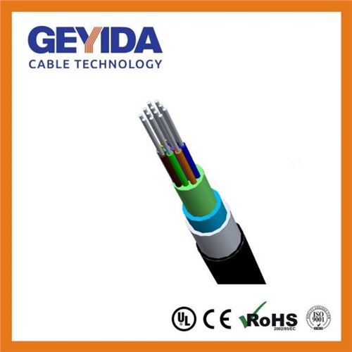
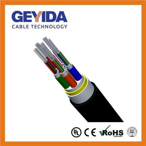
Structure | ||||||||
Description | Filling Gel、Color Coating Fiber、Cable Sub-unit、Strength Member、Ripcord、PE Tape、Jacket. | |||||||
Fiber | SM: G652D、G655、G657 Or other single-mode optical fibers. | |||||||
Strength Member | Aramid yarn or other high strength yarn. | |||||||
Jacket | Materials: low smoke halogen-free flame retardant polyolefin (LSZH) or other materials | |||||||
Features | ||||||||
Application | The dielectric cables for ducts are used for FTTH and long haul networks. | |||||||
Characteristic | Good mechanical and environmental performance. | |||||||
Temperature | -20℃~+60℃ | |||||||
Parameter | ||||||||
Fiber Count | Cable Dimension(mm) | Cable weight | Tensile(N) | Crush(N/10cm) | Bending radius(mm) | |||
Long Term | Short Term | Long Term | Short Term | Static | Dynamic | |||
12 | 3.5 | 13.0 | 100 | 200 | 300 | 1000 | 10D | 20D |
24 | 8.0 | 54.5 | 200 | 400 | 300 | 1000 | 10D | 20D |
48 | 8.0 | 57.5 | 200 | 400 | 300 | 1000 | 10D | 20D |
Options
Cable Dimension: The nominal cable dimension,or other customized dimension:
Delivery Length: 1.0km or 2.0km, or other customized length;
Other requirements: other customized special request.
Sheath Marking
The outer sheath is marked in 1 meter intervals as follows: According to Customer's Requirements
4 Fiber cable Characteristic
4.1 Fiber glass characteristic
The geometric, optical and mechanical properties of the fiber in the cable are shown in the following table.
Table 1 Fiber Parameters
Character | Items | Unit | Specification | |||
Optic Character | ||||||
Attenuation | 1310nm | dB/km | ≤0.34 | |||
≤0.34 | ||||||
≤0.20 | ||||||
≤0.24 | ||||||
Relative wavelength attenuation change @1310nm | 1285~1330nm | dB/km | ≤0.03 | |||
Dispersion wavelength range | 1285~1340nm | PS/(nm.km) | -3.0~3.0 | |||
Zero dispersion wavelength | nm | 1302~1322 | ||||
Zero dispersion slope | PS/(n㎡.km) | ≤0.092 | ||||
Polarization mode dispersion coefficient PMD | PS/ PS/ PS/ | ≤0.1 | ||||
Cable Cutoff Wavelength | nm | ≤1260 | ||||
Mode Field Diameter | 1310nm | um | (8.6~8.8)±0.4 | |||
9.8±0.5 | ||||||
Effective group refractive index | 1310nm | 1.466 | ||||
1.467 | ||||||
Attenuation discontinuity | 1310nm | dB | ≤0.02 | |||
≤0.02 | ||||||
Geometric features | ||||||
Cladding diameter | um | 125.0±0.7 | ||||
Cladding Non-Circularity | % | ≤0.8 | ||||
Coating Diameter | um | 245±7 | ||||
Core-Cladding Concentricity Error | um | ≤10.0 | ||||
Coating Non-Circularity | % | ≤6.0 | ||||
Cladding-Coating Concentricity Error | um | ≤0.5 | ||||
Warp degrees(radus) | m | ≥4 | ||||
Environmental features | ||||||
Item | Additional attenuation | |||||
1310nm | 1550nm | 1625nm | ||||
Temperature cycle | -60℃~+85℃ | dB/km | ≤0.03 | ≤0.03 | ≤0.03 | |
Temperature and humidity cycle | -10℃~85℃, 98% relative humidity | dB/km | ≤0.03 | ≤0.03 | ≤0.03 | |
Flooding | 23℃,30days | dB/km | ≤0.03 | ≤0.03 | ≤0.03 | |
Hot and humid | 85℃ 85℃relative humidity 30 days | dB/km | ≤0.03 | ≤0.03 | ≤0.03 | |
Dry heat aging | 85℃ | dB/km | ≤0.03 | ≤0.03 | ≤0.03 | |
Mechanical preformance | ||||||
Screen tension | GPa | |||||
Macro bending additional damping | 10 cycleФ15mm | dB | 1550nm≤0.03 | |||
1cycle Ф10mm | dB | 1550nm≤0.1 | ||||
1cycle Ф7.5mm | dB | 1550nm≤0.5 | ||||
Coating stripping force | Typical average | N | 1.3≤F≤8.9 | |||
Peak | 1≤F≤5 | |||||
Dynamic fatigue parameters (Nd, Typical values) | ≥20 | |||||
Dynamic tensile strength | Weibull Probability 50% | GPa | ≥3.8 | |||
Weibull Probability 15% | GPa | ≥3.14 | ||||
4.2 Optical Fiber Cable Characteristic
4.2.1 Fiber cable Mechanical Test
See the table below the minimum allowed cable tensile force and flattening
Table 2 Fiber Cable Mechanical Test
Mechanical type | Tension (N) | Crush (N/100mm) | Recommended use |
Short | 2800 | 1000 | Span 100~120m |
2200 | 1000 | Span 60~80m | |
960 | 1000 | Ducts、FTTH | |
Long | 960 | 300 | Span 100~120m |
750 | 300 | Span 60~80m | |
320 | 300 | Ducts、FTTH |
4.2.1.1 Tensile
The test method is IEC60794-1-2 method E1, the chuck diameter is about 30 times the cable diameter, the test length is larger than 50m, the tensile rate is 100mm/min, and the 5min is continued under the specified transient tensile force. Qualification criteria: under long-term allowable tensile force, the fiber has no obvious additional attenuation and strain less than 0.2%; strain is not greater than 0.6% under transient tension, no obvious residual additional attenuation, and no visible cracking of sheath.
4.2.1.2 Crush
The test method is IEC60794-1-2 E3, 1min is applied under flat pressure for a short time, and the number of flattening is at least 3 times (the flattening points are at least 500mm away from each point). Qualification criteria: there is no obvious additional attenuation in the optical fiber under the long squash, and the fiber does not break under the transient flattening, and the sheath does not see visible cracking。
4.2.1.3 Impact
The test method is IEC60794-1-2 method E4; the force is applied in the flat direction, the middle block is the cylinder with radius R12.5mm, the hammer weight is 1N, the hammer drop height is 1m, and the impact times are at least 3 times (the impact points are at least 500mm away from each point). Qualification criteria: the fiber is not broken, and the sheath does not see visible cracking.
4.2.1.4 Repeated Bending
The test method is the IEC60794-1-2 method E6; the axis diameter is 20 times the cable diameter; the load is 40N; the L value is 500mm; the bending times is 100 times. Qualification criteria: no apparent residual attenuation in optical fiber and no visible visible crack in the sheath。
4.2.1.5 Torsion
The test method is IEC60794-1-2 method E7, the axial tension is 20N, the torsion length is 1m, the torsion angle is + 180 degrees (not less than 30 times per minute), and the number of twisting times is 10 times. Qualification criteria: fiber is not broken, and the sheath does not see visible cracking。
4.2.1.6 Bend
Test method for IEC60794-1-2 E11A method; mandrel diameter is 20 times the cable diameter; dense number is 6 cycles per round; 10 cycles. Qualification criteria: the fiber is not broken, and the sheath does not see visible cracking.
4.2.1.7 Abrasion
The test method is the method of E2B "mark wear" in the IEC60794-1- 2 method 2; the load is 10N; the cycle number is not less than 5 times. Qualification criteria: visually still recognizable coat signs.
4.2.2 Environmental performance of optical cable
4.2.2.1 High and low temperature cycle test
Test method for IEC60794-1-2 F1 method; the specimen length is sufficient to obtain the attenuation measurement accuracy required (usually less than 2km); the temperature range of the test temperature range lower limit and upper limit of TA TB, and in accordance with the relevant standards and customer requirements, high temperature of 70 degrees, low temperature is -40 DEG C; the holding time is not less than 8h 2 cycles; attenuation; monitoring is second according to the monitoring method of IEC60793-1-4 "attenuation changes in optical fiber transmission part: backscatter monitoring law" provisions. During the test, the uncertainty of monitoring results caused by the repeatability of the monitoring instrument is better than that of 0.02dB/km. When the absolute value of the attenuation change of the fiber is not more than 0.02dB/km, there is no obvious change in attenuation. When the attenuation is allowed to change, it should be understood that the value is included in the uncertainty. The attenuation change monitoring of single mode fiber should be carried out at 1550nm wavelength, and the attenuation change monitoring of multimode fiber should be carried out at 850nm and / or 1300nm wavelengths. Qualification criteria: optical fiber cable temperature additional attenuation is the difference of fiber attenuation at suitable temperature relative to 20 degree temperature, for single mode is not greater than 0.40dB/km, and for multimode is not greater than 0.60dB/km.
4.2.2.2 Flame retardancy
4.2.2.2.1 Flame retardancy
Without.
4.2.2.2.2 Smoke density
The smog released by the optical fiber cable should make the transmittance less than 50%。
4.2.2.2.3 Corrosive
The pH value of the gas produced by the optical fiber cable is not less than 4.3, and the conductivity is not more than 10 mu S/mm。
4.2.2.2.4 Bending at low temperature
The fiber cable of class a temperature characteristic is capable of winding at -15 C at low temperature. The cable does not crack in the test.
4.2.2.3 Structural integrity and sheath integrity of optical fiber cable
Visual inspection of the integrity and sheath integrity of the cable structure at least 100mm from the cable end.
4.2.3 Physical properties of cable sheath
4.2.3.1 Basic characteristics
The mechanical and physical characteristics of the inner sheath shall be in accordance with the provisions of the table below.
Table 3 Mechanical And Physical Characteristics
No | Item | Unit | Index |
FR LSZH | |||
1 | Prior to thermal aging of tensile strength (minimum value) | MPa | 10.0 |
The rate of change before and after thermal aging|TS| (max)) | % | 20 | |
Temperature of thermal aging treatment | ℃ | 100±2 | |
Heat aging treatment time | h | 24×10 | |
2 | Fracture elongation before thermal aging treatment (minimum value) | % | 125 |
After heat aging treatment (minimum) | % | 100 | |
The rate of change before and after thermal aging|EB| (max) | % | 20 | |
Temperature of thermal aging treatment | ℃ | 100±2 | |
Time of thermal aging treatment | h | 24×10 | |
Heat shrinkage rate | % | 5 | |
Heat treatment temperature | ℃ | 85±3 | |
Heat treatment time | h | 4 | |
4 | Thermal shock resistance | Surface no crack | |
Heat treatment temperature | ℃ | 150±2 | |
Heat treatment time | h | 1 | |
5 | Compressive properties at high temperature (minimum median) | % | 50 |
Heat treatment temperature | ℃ | 80±2 | |
Heat treatment time | h | 16 | |
6 | Environmental stress cracking (50 C, 96 h) (failure number/ number of samples) | PCS | 0/10 |
The mechanical and physical characteristics of the outer sheath should be in accordance with the provisions of the table below。
Table 4 Mechanical And Physical Characteristics
No | Item | Unit | Index | |
MDPE | HDPE | |||
1 | Prior to thermal aging of tensile strength (minimum value) | MPa | 12.0 | 16.0 |
The rate of change before and after thermal aging|TS| (max)) | % | 20 | ||
Temperature of thermal aging treatment | ℃ | 100±2 | ||
Heat aging treatment time | h | 24×10 | ||
2 | Fracture elongation before thermal aging treatment (minimum value) | % | 350 | |
After heat aging treatment (minimum) | % | 300 | ||
The rate of change before and after thermal aging|EB| (max) | % | 20 | ||
Temperature of thermal aging treatment | ℃ | 100±2 | ||
Time of thermal aging treatment | h | 24×10 | ||
3 | Heat shrinkage rate | % | 5 | |
Heat treatment temperature | ℃ | 115±3 | ||
Heat treatment time | h | 4 | ||
4 | Environmental stress cracking (50 C, 96 h) (failure number/ number of samples) | PCS | 0/10 | |
4.2.3.2 Other
The sheath material of hydrogen halide gas content is less than 5mg/g.
4.2.4 Other properties of optical fiber cable
4.2.4.1 Service life of optical fiber cable
Fiber-optic cable life is more than 15 years.
4.2.4.2 Optical cable outer diameter and sheath thickness
6 core Module and 12 core Module tube, two specifications Module optical cable size parameters see the next table.
Table 5 Module Optical Cable Size
Capacity-Fiber count | Modularity | Module Diameter | Module Count | Outer Diameter | FRP Diameter |
12 | 2OF/Module | 0.9 | 6 | 8 | 1.0mm*4 |
24 | 2OF/Module | 0.9 | 12 | 9 | 1.0mm*4 |
36 | 2OF/Module | 0.9 | 18 | 10 | 1.0mm*4 |
48 | 2OF/Module | 0.9 | 24 | 11.5 | 1.0mm*4 |
72 | 2OF/Module | 0.9 | 36 | 13 | 1.0mm*4 |
96 | 2OF/Module | 0.9 | 48 | 14.5 | 1.0mm*4 |
12 | 4OF/Module | 1.1 | 3 | 7.0 | 1.0mm*4 |
24 | 4OF/Module | 1.1 | 6 | 8.0 | 1.0mm*4 |
36 | 4OF/Module | 1.1 | 9 | 10.5 | 1.0mm*4 |
48 | 4OF/Module | 1.1 | 12 | 11.5 | 1.0mm*4 |
72 | 4OF/Module | 1.1 | 18 | 12.5 | 1.0mm*4 |
96 | 4OF/Module | 1.1 | 24 | 13.0 | 1.0mm*4 |
12 | 6OF/Module | 1.1 | 2 | 7 | 1.0mm*4 |
24 | 6OF/Module | 1.1 | 4 | 7 | 1.0mm*4 |
36 | 6OF/Module | 1.1 | 6 | 8 | 1.0mm*4 |
48 | 6OF/Module | 1.1 | 8 | 8 | 1.0mm*4 |
72 | 6OF/Module | 1.1 | 12 | 11.5 | 1.0mm*4 |
96 | 6OF/Module | 1.1 | 16 | 11.5 | 1.0mm*4 |
144 | 6OF/Module | 1.1 | 24 | 13 | 1.0mm*4 |
12 | 12OF/Module | 1.3 | 1 | 7.0 | 1.0mm*4 |
24 | 12OF/Module | 1.3 | 2 | 7 | 1.0mm*4 |
36 | 12OF/Module | 1.3 | 3 | 7 | 1.0mm*4 |
48 | 12OF/Module | 1.3 | 4 | 8 | 1.0mm*4 |
72 | 12OF/Module | 1.3 | 6 | 10 | 1.0mm*4 |
96 | 12OF/Module | 1.3 | 8 | 11.5 | 1.0mm*4 |
144 | 12OF/Module | 1.3 | 12 | 11.5 | 1.0mm*4 |
192 | 12OF/Module | 1.3 | 16 | 13 | 1.0mm*4 |
288 | 12OF/Module | 1.3 | 24 | 16 | 1.0mm*4 |
4.2.4.3 Fiber & Tube Color
Color Identification of Fiber
Table 6 Color Identification Of Fiber
No | 1 | 2 | 3 | 4 | 5 | 6 | 7 | 8 | 9 | 10 | 11 | 12 |
Color | Blue | Orange | Green | Brown | Grey | White | Red | Black | Yellow | Violet | Pink | Aqua |
Table 7 Color Identification Of Tube
No | 1 | 2 | 3 | 4 | 5 | 6 | 7 | 8 | 9 | 10 | 11 | 12 |
Color | Blue | Orange | Green | Brown | Grey | White | Red | Black | Yellow | Violet | Pink | Aqua |
4.2.4.4 Fiber optic appearance and color
The smooth surface of the circular sheath, the section without visual cracks, bubbles and defects such as trachoma. Sheath color is black.
4.2.4.5 sheath logo and meter error
The optical cable is a permanent sign on the sheath surface along the length direction, which does not affect any performance of the optical cable. When the printing direction is left to the right, the print is in the following cable. The distance between the beginning points of the adjacent signs is not less than 1m. The contents of the logo include the type of fiber optic cable products, the length of meter meter, the name of the manufacturer (or the code name) or (and) trademark and manufacturing year or batch number, etc. The mark is clear and is firmly adhered to the sheath. It is still recognizable after the wear test. Sign by meters in length deviations from 0 to 1%, in order to ensure the real length of not less than the length of the meter.
4.2.4.6 packaging and transportation
Fiber optic cable products are installed on the optical cable delivery plate, and the diameter of the core is not less than 20 times the diameter of the cable and is not less than 90mm. The product is also attached with appropriate protection, such as packing. Each disk has only one manufacturing length, and it has been marked on the optical cable tray and the packaging box: the manufacturer's name and product label, cable mark, cable length, gross weight (kg), manufacturing date and / or production batch number, and other signs to ensure the safety of storage and transportation.
Cable transport and storage should pay attention: do not make the cable reel in flat position, no box cable tray shall be stacked; rolling rotating disc cable should be according to the direction of the arrow reel label, not long rolling; shall be subjected to collision, extrusion and any mechanical damage; to prevent damp and long time exposure; storage temperature should be controlled at -5 DEG +50 DEG C, if exceed the allowable temperature range should be inspected before delivery.
5 Other raw materials
Main raw material properties - aramid yarn
Table 8 The Performance Index Of Common Aramid Yarn
KEVLAR | Line density (g/10000m) | Modulus (gpd) | Fracture strength (lb.) | Tensile strength | Elongation (%) | Bearing section (10-2mm2) | Diameter |
KEVLAR49 | 1580 | 850 | 71 | 22.8 | 2.50 | 11.3 | 0.42 |
3160 | 880 | 138 | 22.1 | 2.38 | 22.6 | 0.60 | |
KEVLAR29 | 440 | 725 | 21 | 24.3 | 3.20 | 3.0 | 0.22 |
1110 | 585 | 50 | 22.7 | 3.30 | 7.5 | 0.35 | |
1 gpd = 12.96 kgf/mm2 = 12.96·106 kgf/m2 = 18.43·103 psi 1 g/tex = 1.44 kgf/mm2 = 1.44·106 kgf/m2 | |||||||
Inquiry


 cc
cc